

Design


Air intake
An intake, or tube, is needed in front of the compressor to help direct the incoming air smoothly into the moving compressor blades. Older engines had stationary vanes in front of the moving blades. These vanes also helped to direct the air onto the blades. The air flowing into a turbojet engine is always subsonic, regardless of the speed of the aircraft itself.
The intake has to supply air to the engine with an acceptably small variation in pressure (known as distortion) and having lost as little energy as possible on the way (known as pressure recovery). The ram pressure rise in the intake is the inlets contribution to the propulsion system overall pressure ratio and thermal efficiency.
The intake gains prominence at high speeds when it transmits more thrust to the airfame than the engine does. Well-known examples are the Concorde and Lockheed SR-71 Blackbird propulsion systems where the intake and engine contributions to the total powerplant were 63%/8%[14] at Mach 2 and 54%/17%[15] at Mach 3+.
Intakes have ranged from 'zero-length'[16] on the Pratt & Whitney TF33 installation in the Lockheed C-141 Starlifter to the twin, 65 feet-long, intakes on the North American XB-70 Valkyrie each feeding three engines with an intake airflow of about 800 lb/sec.
Compressor
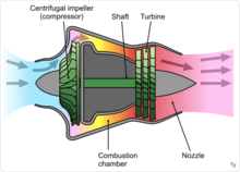
The compressor is driven by the turbine. It rotates at high speed, adding energy to the airflow and at the same time squeezing (compressing) it into a smaller space. Compressing the air increases its pressure and temperature. The smaller the compressor, the faster it turns. At the large end of the range, the GE-90-115 fan rotates at about 2,500 RPM, while a small helicopter engine compressor rotates around 50,000 RPM.
Turbojets supply bleed air from the compressor to the aircraft for the environmental control system, anti-icing, and fuel tank pressurization, for example. The engine itself needs air at various pressures and flow rates to keep it running. This air comes from the compressor, and without it, the turbines would overheat, the lubricating oil would leak from the bearing cavities, the rotor thrust bearings would skid or be overloaded, and ice would form on the nose cone. The air from the compressor, called secondary air, is used for turbine cooling, bearing cavity sealing, anti-icing, and ensuring that the rotor axial load on its thrust bearing will not wear it out prematurely. Supplying bleed air to the aircraft decreases the efficiency of the engine because it has been compressed, but then does not contribute to producing thrust. Bleed air for aircraft services is no longer needed on the turbofan-powered Boeing 787.
Compressor types used in turbojets were typically axial or centrifugal. Early turbojet compressors had low pressure ratios up to about 5:1. Aerodynamic improvements including splitting the compressor into two separately rotating parts, incorporating variable blade angles for entry guide vanes and stators, and bleeding air from the compressor enabled later turbojets to have overall pressure ratios of 15:1 or more. For comparison, modern civil turbofan engines have overall pressure ratios of 44:1 or more. After leaving the compressor, the air enters the combustion chamber.
Combustion chamber
The burning process in the combustor is significantly different from that in a piston engine. In a piston engine, the burning gases are confined to a small volume, and as the fuel burns, the pressure increases. In a turbojet, the air and fuel mixture burn in the combustor and pass through to the turbine in a continuous flowing process with no pressure build-up. Instead, a small pressure loss occurs in the combustor.
The fuel-air mixture can only burn in slow-moving air, so an area of reverse flow is maintained by the fuel nozzles for the approximately stoichiometric burning in the primary zone. Further compressor air is introduced which completes the combustion process and reduces the temperature of the combustion products to a level which the turbine can accept. Less than 25% of the air is typically used for combustion, as an overall lean mixture is required to keep within the turbine temperature limits.
Turbine
Hot gases leaving the combustor expand through the turbine. Typical materials for turbines include inconel and Nimonic.[17]The hottest turbine vanes and blades in an engine have internal cooling passages. Air from the compressor is passed through these to keep the metal temperature within limits. The remaining stages do not need cooling.
In the first stage, the turbine is largely an impulse turbine (similar to a pelton wheel) and rotates because of the impact of the hot gas stream. Later stages are convergent ducts that accelerate the gas. Energy is transferred into the shaft through momentum exchange in the opposite way to energy transfer in the compressor. The power developed by the turbine drives the compressor and accessories, like fuel, oil, and hydraulic pumps that are driven by the accessory gearbox.
Nozzle
After the turbine, the gases expand through the exhaust nozzle producing a high velocity jet. In a convergent nozzle, the ducting narrows progressively to a throat. The nozzle pressure ratio on a turbojet is high enough at higher thrust settings to cause the nozzle to choke.
If, however, a convergent-divergent de Laval nozzle is fitted, the divergent (increasing flow area) section allows the gases to reach supersonic velocity within the divergent section. Additional thrust is generated by the higher resulting exhaust velocity.
Thrust augmentation
Thrust was most commonly increased in turbojets with water/methanol injection or afterburning. Some engines used both at the same time.
Liquid injection was tested on the Power Jets W.1 in 1941 initially using ammonia before changing to water and then water/methanol. A system to trial the technique in the Gloster E.28/39 was devised but never fitted.[18]
Afterburner
An afterburner or "reheat jetpipe" is a combustion chamber added to reheat the turbine exhaust gases. The fuel consumption is very high, typically four times that of the main engine. Afterburners are used almost exclusively on supersonic aircraft, most being military aircraft. Two supersonic airliners, Concorde and the Tu-144, also used afterburners as does Scaled Composites White Knight, a carrier aircraft for the experimental SpaceShipOne suborbital spacecraft.
Reheat was flight-trialled in 1944 on the W.2/700 engines in a Gloster Meteor I
Source :


0 comments